Most engineers who deploy to Kubernetes daily have a solid working mental model of pods, Deployments, and Services. The deeper architecture beneath those abstractions tends to get less attention. That gap is manageable until you are evaluating an EKS (Elastic Kubernetes Service) contract, designing a multi-cluster topology, or debugging a scheduler backlog at 2 a.m. on a Saturday. At that point, the gaps in understanding become costly.
This guide fills in that picture. It covers how the control plane, data plane, etcd (a distributed key-value store), kube-scheduler, kubelet, and CNI (Container Network Interface) plugins fit together as a system, what breaks when they do not work as expected, and what “managed Kubernetes” actually means for your day-to-day operational responsibilities.
The Core Mental Model: Brain and Muscle
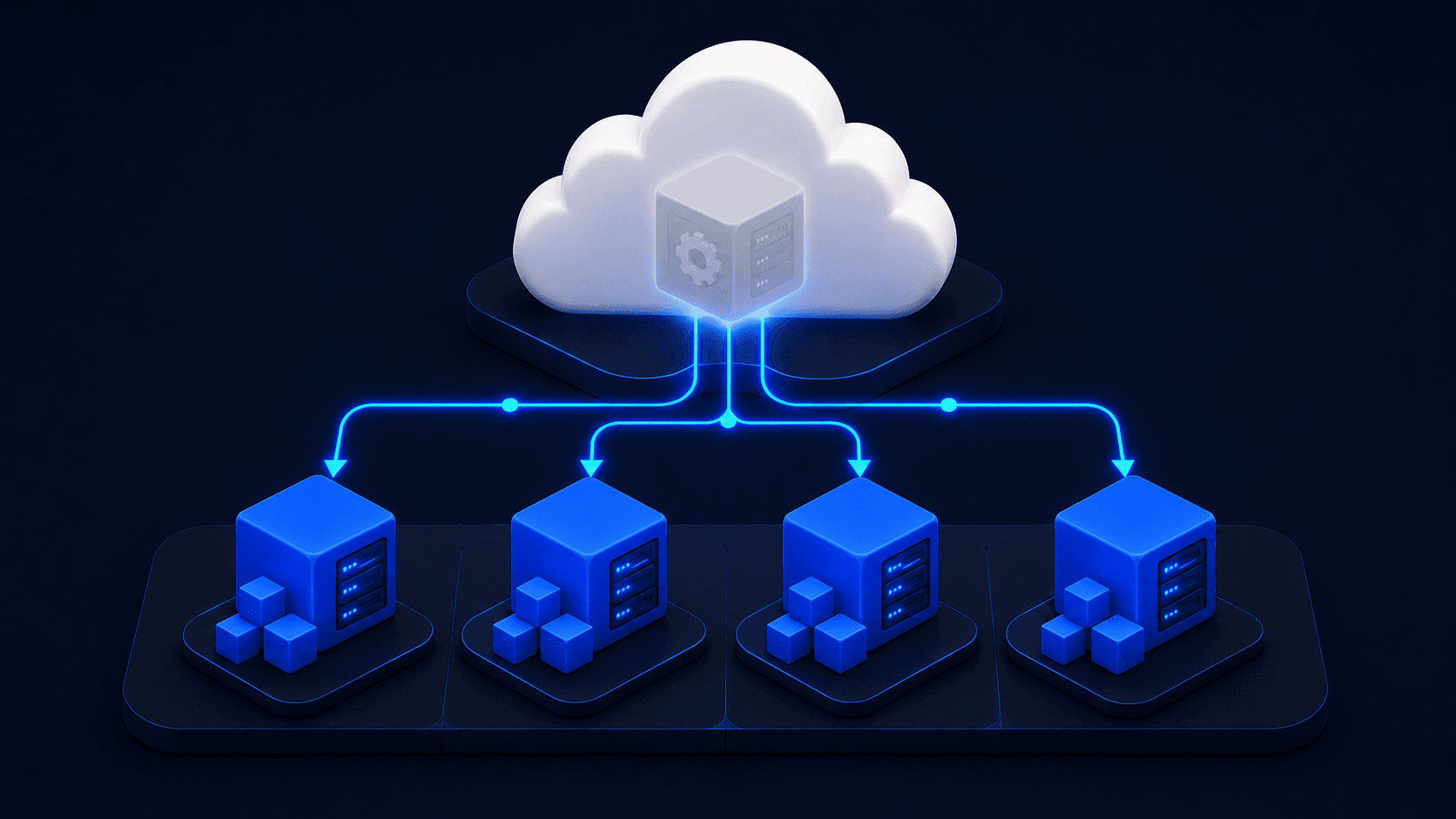
Kubernetes splits into two planes: the control plane, which owns desired state, and the data plane, which owns the actual state.
The control plane is where you declare that you want three replicas of your API server and where Kubernetes decides which nodes those pods should run on.
The data plane is the machinery on every node that takes orders from the control plane and makes containers exist.
Every Kubernetes component lives on one side of this line or the other.
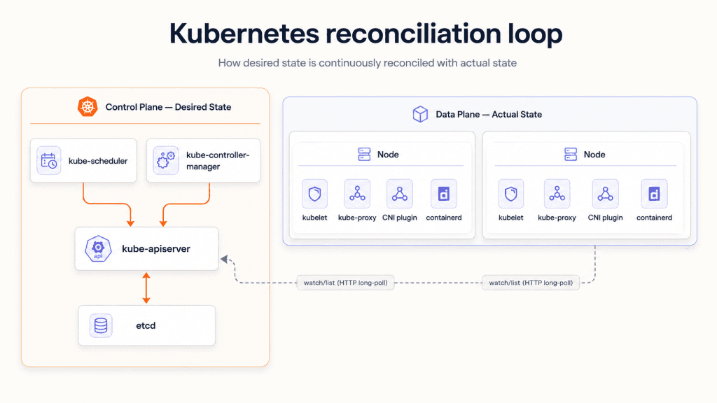
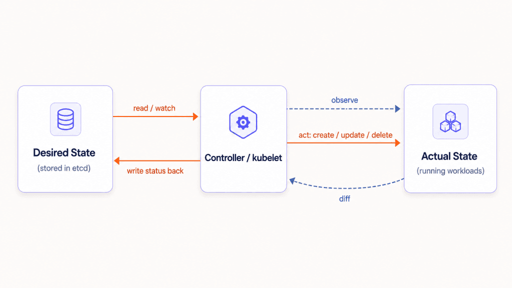
The single organizing pattern that holds all of this together is the reconciliation loop. Every Kubernetes component has one of two roles: it either asserts desired state by writing to the API server, or it converges actual state toward desired state by reading from the API server and acting on what it finds. A controller watches for resource changes and drives the cluster toward the declared goal. A kubelet watches for PodSpecs assigned to its node and drives the container
This split (between the control plane and the data plane) defines your blast radius during incidents.
A control plane failure takes two main forms: etcd losing quorum (where enough nodes in the etcd cluster have failed that the remaining nodes can no longer agree on cluster state), or the API server going down. Either way, all scheduling and API writes stop. Running pods, however, keep running. The kubelet does not require constant contact with the control plane; it converges to the desired state and holds it locally, so existing workloads continue unaffected until the control plane recovers.
A data plane failure produces the opposite situation. Pods die and workloads become unavailable, yet the API server stays fully responsive, meaning you can still query cluster state and investigate what happened.
Keeping this boundary clear is fundamental to sound disaster recovery design.
Inside the Control Plane
The Kubernetes control plane consists of four components: kube-apiserver, etcd, kube-scheduler, and kube-controller-manager — each with a distinct role in managing desired cluster state.
kube-apiserver
It is the only stateful read/write endpoint in the cluster. Every other component (including controllers talking to each other) routes through it. It doesn’t push updates; consumers establish long-lived HTTP watch connections via the watch=true query parameter and receive a stream of change events. This is how kubelet learns about new PodSpecs assigned to its node: polling is replaced by a persistent watch that fires when anything changes.
etcd
It is a distributed key-value store built on the Raft consensus algorithm. The API server writes here and reads from its in-memory cache. Raft requires a majority quorum to commit a write: with a 3-node etcd cluster, you can lose 1 node and keep writing; with 5 nodes, you can lose 2. This is why you run odd-numbered etcd clusters. An even-numbered cluster (say, 4 nodes) has the same fault tolerance as 3 — it can only lose 1 — but you’re paying for the extra node with higher write latency.
kube-scheduler
It works in two phases. In the first phase, filtering, it identifies which nodes satisfy a pod’s resource requests, affinity rules, and taints/tolerations. In the second phase, scoring, it ranks the remaining eligible nodes and selects the best fit.
Two recent additions improve scheduler performance at scale. Pod Scheduling Readiness, stable since Kubernetes v1.30, prevents pods that are not yet schedulable from clogging the scheduler queue while waiting for external conditions to be met. QueueingHint, introduced in Kubernetes v1.32, reduces unnecessary rescheduling attempts by allowing plugins to signal whether a given cluster-state change is actually relevant to a queued pod.
kube-controller-manager
It is a single process that hosts dozens of independent control loops, including the ReplicaSet controller, the Node controller, the Endpoints controller, and many more. Each loop watches the API server for changes to its specific resource type and drives actual state toward desired state.
Every CRD (Custom Resource Definition)-based operator you have ever deployed follows the same pattern. A CRD lets you extend Kubernetes with your own resource types, and any operator built on one uses the same reconciliation loop applied to those custom resources.
Inside the Data Plane
The Kubernetes data plane runs on every node and consists of kubelet, kube-proxy, a CNI plugin, and a container runtime. These components execute the desired state declared by the control plane.
kubelet
The kubelet runs on every node with a focused responsibility: it watches the API server for PodSpecs assigned to its node and instructs the container runtime to run them. It also handles volume reconciliation, keeping the storage attached to pods in sync with their declared state.
The VolumeManager reconstruction process, stable since Kubernetes v1.30, ensures that volume state is correctly rebuilt after a kubelet restart without requiring pod restarts. Beyond workload management, the kubelet reports node-level resource consumption (CPU, memory, and disk) back to the API server, which is how the scheduler knows when a node is full and should stop receiving new pods.
kube-proxy
It runs on each node and maintains iptables or IPVS (IP Virtual Server) rules to implement Service ClusterIP and NodePort routing. It operates at Layer 4 (the transport layer), routing TCP/UDP connections to the correct pod IP address.
The kube-proxy and the CNI (Container Network Interface) plugin handle distinct parts of the networking stack. The kube-proxy owns service routing, while the CNI plugin owns pod-to-pod Layer 3 (network layer) connectivity. Each handles a different layer with a different responsibility.
CNI plugins
CNI (Container Network Interface) plugins follow a simple contract: Kubernetes calls a binary when a pod starts or stops, and that binary handles IP address assignment and network wiring. The three dominant implementations differ significantly:
- Flannel uses a VXLAN (Virtual Extensible LAN) overlay and is the simplest option. It does not enforce NetworkPolicy, so clusters that require network segmentation will need a different solution.
- Calico supports either BGP (Border Gateway Protocol) routing, which avoids an overlay and reduces latency, or VXLAN, and enforces full NetworkPolicy. It is the most common choice for production clusters that require network isolation.
- Cilium uses eBPF (extended Berkeley Packet Filter) to implement networking directly in the kernel without iptables, reducing overhead and enabling Layer 7 (application layer) policy enforcement and observability. In some configurations, Cilium replaces kube-proxy entirely. It also supports a native cluster-mesh mode for cross-cluster pod networking, which becomes relevant when designing multi-cluster topologies.
Your CNI choice directly constrains what multi-cluster networking is possible without a service mesh, so it is worth settling that question before committing to one.
Containerd
Containerd is the container runtime most clusters use, integrated with Kubernetes through the CRI (Container Runtime Interface). When the kubelet needs to start a container, it passes a container image reference to containerd via the CRI. Containerd then takes over, handling image pulls, namespace isolation, and cgroup (control group) setup, which controls how much CPU and memory a container can use.
User namespaces, in beta since Kubernetes v1.30, add an additional isolation layer by mapping container UIDs (User Identifiers) to unprivileged host UIDs. This is worth enabling if your threat model includes container breakout, as it limits what a compromised container can do on the host.
etcd Is the Hardest Component to Get Right
etcd is the single source of truth for all Kubernetes cluster states. Most engineers treat it as a black box: it stores state, the API server talks to it, and that is enough. That assumption holds until something goes wrong.
etcd uses the Raft consensus algorithm to keep its cluster of nodes in sync. Raft requires one node to act as the leader at all times. The leader receives all write requests, replicates them to follower nodes, and commits a write only after a majority of nodes acknowledge it.
Write latency in etcd is sensitive to underlying hardware because etcd calls fsync after every write to guarantee durability. fsync forces the operating system to flush data to disk before confirming the write, which means disk speed directly caps write throughput. On a spinning disk with a 5ms fsync latency, API server write throughput is hard-capped at roughly 200 operations per second. On NVMe (Non-Volatile Memory Express) with sub-millisecond fsync, that ceiling essentially disappears. If your API server feels slow and you have not yet checked etcd’s disk I/O, that is the right place to start.
For backups, etcdctl snapshot save /backup/etcd-$(date +%Y%m%d%H%M%S).db writes a point-in-time snapshot. Run this hourly minimum in production. Verify the snapshot immediately:
etcdctl snapshot status /backup/your-snapshot.db --write-out=table
Store the snapshot off-cluster. If etcd loses quorum, you cannot recover it without either a valid snapshot or manual Raft surgery — and manual Raft surgery is exactly as unpleasant as it sounds.
etcdctl endpoint status --cluster -w table
That command shows which member is the leader, each member’s Raft index, their database size, and any errors. If db size approaches 8 GB, compact and defrag immediately. etcd will refuse writes if it hits its space quota.
When the control plane’s write path is unavailable, existing pods keep running because kubelet drives data plane state independently once a pod is scheduled. No new pods schedule, no ConfigMaps update, no Secrets rotate, and no controller can act. Your RTO for “can’t schedule new pods” equals the time to restore etcd quorum. Design around that number explicitly.
Multi-Cluster Architecture: Patterns and Trade-offs
Multi-cluster Kubernetes architecture distributes workloads across independent clusters. Teams adopt this approach for four main reasons, and each of these patterns comes with distinct operational consequences as explained below:
- Blast radius isolation: a failure in one cluster, such as
etcdlosing quorum, does not affect workloads running in another region. - Regulatory compliance: data residency laws such as GDPR (General Data Protection Regulation) and HIPAA (Health Insurance Portability and Accountability Act) often require data to stay within specific jurisdictions.
- Geo-latency reduction: running clusters closer to users in different regions reduces round-trip times and improves response times.
- Environment separation: running production and staging as fully independent clusters rather than as namespaces within a shared cluster reduces the risk of one environment affecting the other.
Two architectural patterns dominate multi-cluster deployments.
Pattern A: Cluster Federation
Tools like KubeFed or Cluster API let a central management cluster push configuration to member clusters via CRDs (Custom Resource Definitions). Each member cluster maintains its own independent control plane, with its own etcd instance and its own scheduler. The federation layer coordinates placement and policy across all of them.
The operational complexity in this pattern shifts to the federation layer itself. Each member cluster’s etcd still requires independent upgrade management and health monitoring, so the total operational burden remains high.
Pattern B: Unified Management Plane Above Kubernetes
A platform layer treats each cluster as a registered location and exposes a single API above all of them. Traffic routing, geo-DNS, and workload placement are handled at the platform layer rather than at the individual Kubernetes scheduler level.
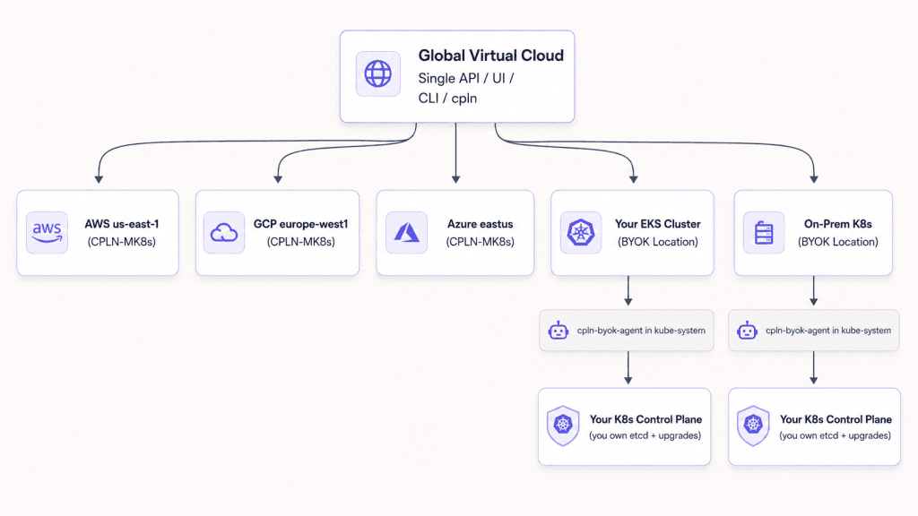
The virtual cloud platform by Control Plane is built around this model. Its GVC (Global Virtual Cloud) abstraction defines a set of Locations, which can be Control Plane-provisioned clusters on AWS, GCP, or Azure, or clusters you already own and operate. The platform handles latency-based geo-routing, priority failover, and cross-location traffic distribution without touching the Kubernetes schedulers running underneath. For BYOK (Bring Your Own Kubernetes) clusters, Control Plane connects via a lightweight agent deployed in the kube-system namespace, meaning your etcd and control plane upgrades remain your responsibility, while everything above that layer is managed by the platform.
The most common gap in multi-cluster designs is cross-cluster networking. CNI (Container Network Interface) plugins are cluster-scoped, meaning Cilium on cluster A has no awareness of pod IPs on cluster B, and Calico on cluster A has no knowledge of cluster B at all.
Bridging that gap requires one of two approaches: a service mesh running in multi-cluster mode, or a dedicated cross-cluster networking tool. Istio in multi-cluster mode is one widely used option, and it is what Control Plane ships as the default service mesh for all registered Locations. Alternatives like Submariner or Skupper address the same problem without a full service mesh.
If you are planning a multi-cluster architecture and have not yet answered how services in cluster A call services in cluster B, that question needs to be resolved before moving forward.
What Managed Kubernetes Actually Abstracts — and What You Still Own
Managed Kubernetes (EKS, GKE, AKS) hands off the control plane — etcd, kube-apiserver, kube-scheduler, and kube-controller-manager — to the cloud provider. You retain ownership of the data plane: node pools, kubelet versions, your CNI plugin or the provider’s default, and cluster-level add-ons like ingress controllers and cert-manager.
The Disaster Recovery (DR) implications are concrete. With EKS (Elastic Kubernetes Service), GKE (Google Kubernetes Engine), or AKS (Azure Kubernetes Service), the provider’s SLA covers API server availability and etcd recovery. Your RTO (Recovery Time Objective) for scheduling failures shrinks to the provider’s failover time, typically minutes, rather than however long it takes your on-call engineer to restore etcd quorum from a snapshot. The trade-off is visibility: you lose direct etcdctl access, cannot tune Raft election timeouts, and must trust the provider’s upgrade sequencing.
Upgrade sequencing is worth understanding even when the provider handles it. In a self-managed cluster, etcd is upgraded before the API server, the API server before the controller-manager, and the control plane before nodes. With a managed control plane, the provider owns that sequence and you only control the node pool upgrade window. Knowing exactly which parts of that sequence you are responsible for matters before you commit to an SLA.
Control Plane operates one layer above EKS, GKE, or AKS. Its GVC (Global Virtual Cloud) is a management plane that sits across multiple Kubernetes clusters simultaneously. Existing clusters can be brought in as BYOK (Bring Your Own Kubernetes) Locations without migrating workloads. The cpln-byok-agent installs into your cluster, registers it with the Control Plane API, and gives you a unified API, CLI, and observability layer including Prometheus and Grafana across AWS, GCP, Azure, and on-premises clusters.
Registering a BYOK cluster is a two-step process. First, create the Location record in the Control Plane console by navigating to Locations, selecting New, entering a unique name, and clicking Create. Second, apply the generated kubectl command to your target cluster. The command contains a time-limited token and must be applied within 5.5 minutes. Once applied, run kubectl get pod -l app=cpln-byok-agent -n kube-system to confirm the agent is coming up, and allow a few minutes for all components to deploy.
For your cluster to qualify as a BYOK Location, it needs:
- At least one nodegroup labeled
cpln.io/nodeType=core - A minimum of 2 CPUs and 8 GB RAM per node (4 CPUs and 16 GB recommended)
- At least 2 nodes (3+ recommended)
- amd64 or arm64 architecture
- One of the three most recent Kubernetes minor releases
- A working load balancer controller
If you’re already running a service mesh, remove it first. Control Plane provisions Istio for you.
Audit Your Cluster Right Now: Three Commands
Don’t wait for an incident to learn what your cluster is running. These three commands give you an immediate read on control plane health, etcd state, and CNI configuration.
kubectl get --raw /readyz
kubectl get --raw '/livez?verbose'
The first returns ok or a list of failed checks. The second breaks down every subsystem (etcd connectivity, post-start hooks, each internal controller) so you can see exactly what’s degraded. Run livez?verbose before an incident and read the output. You want to know what “healthy” looks like before you’re comparing it to “unhealthy” at 2 a.m.
etcdctl endpoint status --cluster -w table
This shows leader state, Raft index, and database size per member. If you run a self-managed cluster and you haven’t checked this in the past 30 days, do it now. If db size is approaching 8 GB, run a compaction (etcdctl compact $(etcdctl endpoint status --write-out="json" | jq '.[0].Status.header.revision')) and then defrag (etcdctl defrag --cluster) before etcd starts refusing writes.
kubectl get pods -n kube-system | grep -E 'cilium|calico|flannel|weave'
Know what you’re running and verify it’s current. If multi-cluster networking is on your roadmap, check whether your CNI supports native cluster-mesh mode. Cilium does; Calico and Flannel require a service mesh or external tooling at cluster boundaries. That answer shapes the rest of your architecture.
If you want to see what a unified management plane looks like without rebuilding your existing clusters, register one as a BYOK Location at console.cpln.io: Locations, then Create, then apply the generated kubectl command. The cpln-byok-agent deploys in minutes and your cluster appears as a Location in the GVC alongside any other registered cloud region or cluster. You can deploy workloads to it immediately through the single Control Plane API.
Final Thoughts
The control plane / data plane split is the frame that makes every other Kubernetes decision legible. etcd quorum determines your write availability floor. Your CNI plugin determines what multi-cluster networking is possible. Managed Kubernetes shifts the control plane off your operational plate, but the data plane is always yours — and upgrade sequencing boundaries matter whether you’re on EKS, on-prem, or both.
If you’re evaluating managed Kubernetes or designing a multi-cluster architecture, start with the architecture. Know what each component does, what breaks when it fails, and what you’re actually handing off when you sign up for a managed offering.
Start free at console.cpln.io to see what managing multiple clusters from a single API looks like in practice.
Frequently Asked Questions
What is the difference between the Kubernetes control plane and data plane?
The control plane manages desired state — it stores configuration in etcd, schedules pods, and runs controllers that reconcile what you declared against what exists. The data plane executes actual state on each node: kubelet, kube-proxy, the CNI plugin, and the container runtime turn PodSpecs into running containers. A control plane failure stops scheduling but leaves running pods intact; a data plane failure kills pods but leaves the API server responsive.
What happens to running pods if the Kubernetes control plane goes down?
Running pods continue to run. kubelet holds the pod state locally after initial scheduling and doesn’t require continuous contact with the API server to keep containers alive. What stops is everything new: no pods schedule, no ConfigMaps update, no Secrets rotate, no controllers act. Your recovery time objective for “can schedule new pods again” equals the time to restore control plane availability.
Why does etcd require an odd number of nodes?
Raft consensus requires a strict majority to commit a write. With 3 nodes, the quorum threshold is 2, so you can lose 1 node and keep writing. With 4 nodes, the quorum threshold is still 3, giving you the same fault tolerance as 3 nodes but higher write latency. With 5 nodes, the quorum threshold is 3, allowing 2 failures. An even-numbered cluster provides no additional fault tolerance over the next lower odd number, so the extra node cost is pure overhead.
What does managed Kubernetes (EKS, GKE, AKS) actually manage?
Managed Kubernetes providers operate the control plane: etcd, kube-apiserver, kube-scheduler, and kube-controller-manager. You retain ownership of the data plane — node pools, kubelet versions, CNI plugin selection, and cluster add-ons like ingress controllers and cert-manager. The provider’s SLA covers control plane availability and etcd recovery; your data plane is always your operational responsibility.
Which CNI plugin should I use for multi-cluster Kubernetes networking?
Cilium is the strongest choice if multi-cluster networking is on your roadmap. It supports native cluster-mesh mode for cross-cluster pod connectivity without a service mesh. Calico and Flannel are cluster-scoped and require either a service mesh in multi-cluster mode (such as Istio) or a dedicated tool like Submariner or Skupper to route traffic across cluster boundaries. Settle this question before picking a CNI — it constrains your entire multi-cluster architecture.
What is the Kubernetes reconciliation loop?
The reconciliation loop is the pattern every Kubernetes component follows: watch the API server for a difference between desired state (stored in etcd) and actual state (running workloads), then act to close that gap. Controllers reconcile resource types like ReplicaSets and Endpoints. kubelet reconciles PodSpecs on its node. Every CRD-based operator uses the same loop applied to custom resources.
How do I check etcd health in a self-managed Kubernetes cluster?
Run etcdctl endpoint status --cluster -w table to see leader state, Raft index, and database size per member. If db size approaches 8 GB, compact and defrag immediately or etcd will refuse writes. For API server subsystem health, run kubectl get --raw '/livez?verbose' to see the status of every internal controller and etcd connectivity in one output.
What is a BYOK Location in Control Plane?
A BYOK (Bring Your Own Kubernetes) Location is an existing Kubernetes cluster registered with the Control Plane platform. Installing the cpln-byok-agent into your cluster’s kube-system namespace registers it as a Location in a Global Virtual Cloud alongside cloud-provisioned clusters on AWS, GCP, or Azure. You retain ownership of that cluster’s etcd and upgrade lifecycle; Control Plane adds a unified API, observability, and cross-location traffic routing above it.