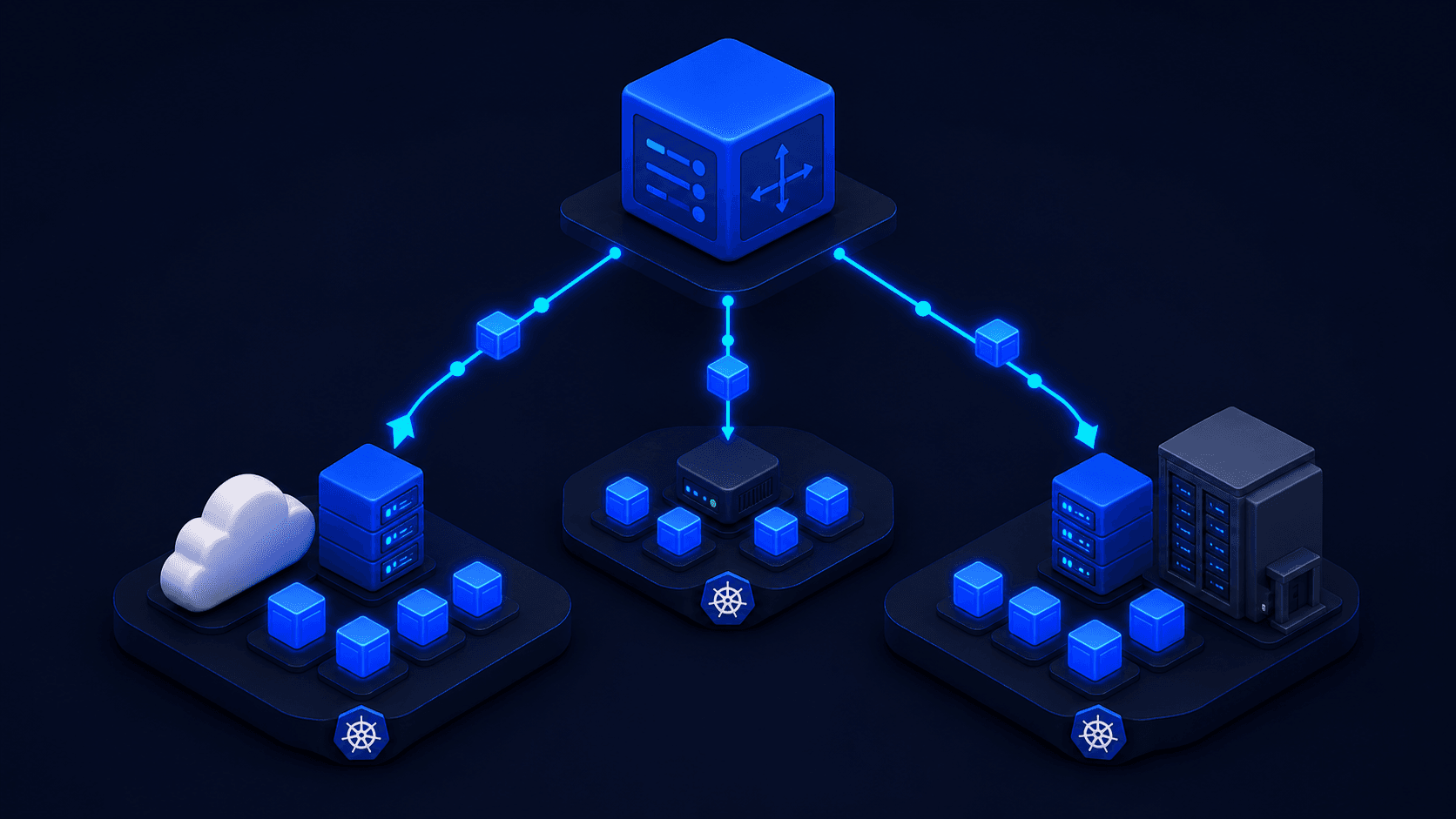
Kubernetes multi-cloud orchestration is the practice of running containerized workloads across AWS, GCP, and Azure using a coordination layer that sits above individual clusters, because raw Kubernetes handles single-cluster lifecycle management only, and stops entirely at the cluster boundary.
Every engineer knows what a pod is. Fewer know exactly what the scheduler evaluates when placing one. And almost no one (until they’ve hit it at 2 a.m.) knows what happens when that pod needs to reach a service in a different cluster. Cross-cluster communication falls outside Kubernetes’s scope entirely.
That’s the delta this article addresses: how the pieces actually work (scheduler internals, DNS resolution boundaries, health probe mechanics) and precisely where raw K8s stops being useful when your workloads span AWS, GCP, and Azure. Once you understand the boundary, you can design around it instead of discovering it mid-incident.
What you’ll learn:
- How Kubernetes desired-state reconciliation, resource-aware placement, and failure recovery actually work internally
- Why the scheduler’s two-phase filtering and scoring loop cannot cross cluster boundaries
- What causes CIDR overlap between EKS and GKE, and the three ways to resolve it
- How CoreDNS scoping and health probe mechanics break down at cluster edges
- What a managed multi-cloud orchestration layer provides that raw K8s cannot
What Container Orchestration Actually Solves
Container orchestration solves three specific problems: desired-state reconciliation, resource-aware placement, and automated failure recovery. Kubernetes does this inside a single cluster by continuously comparing declared intent against observed reality and reconciling any divergence. The control plane components (API server, etcd, scheduler, and controller manager) never operate across cluster boundaries.
Desired-state reconciliation means you describe what you want (three replicas of your API service, each with 256 Mi of memory, placed on separate nodes) and the system continuously works to make reality match that description. If a node disappears, the reconciliation loop detects the divergence from desired state and schedules new pods to compensate. You never told the system to restart anything. It figures that out from the delta between declared intent and observed reality.
Resource-aware placement means the scheduler evaluates whether a Pod’s requested CPU and memory fit on a node, then ranks feasible nodes using configured scoring plugins. This resembles a bin-packing problem conceptually, but Kubernetes does not always optimize for maximum density by default. True bin-packing behavior depends on scheduler configuration, such as NodeResourcesFit with MostAllocated or RequestedToCapacityRatio. An imperative script would need to query current node utilization, calculate remaining headroom, and make a placement decision. The scheduler does this for every pod, every time, using a consistent algorithm.
Automated failure recovery covers the rest: restarting containers that fail liveness or startup checks, removing unready pods from service endpoints, rescheduling pods evicted from drained nodes, and rolling out deployments without downtime.
The Kubernetes control plane that makes this work has four core components. The API server is the single source of truth, and every component reads from and writes to it directly. etcd is the distributed key-value store that backs the API server’s state, where your pod specs, service definitions, and config maps actually live. The scheduler reads unscheduled pods from the API server and writes node assignments back to it. The controller manager runs a collection of reconciliation loops (one for ReplicaSets, one for deployments, one for endpoints, and so on), each watching the API server for changes and taking action to converge actual state toward declared state.
This declarative model beats imperative scripts because the watch-and-reconcile loop is resilient to partial failures. An imperative script that applies a configuration change and then encounters a network timeout leaves the system in an unknown state. A declarative reconciliation loop that’s interrupted partway through runs again, and the system converges eventually, even across failures.
Why Kubernetes Won the Container Orchestration Wars
Kubernetes became the dominant container orchestration platform for three reasons unrelated to simplicity: CRD extensibility made it the integration layer for the entire cloud-native ecosystem, CNCF backing created gravitational network effects, and managed offerings like EKS, GKE, and AKS removed the cluster-admin burden. Its design scope remained single-cluster lifecycle management throughout, and that boundary is exactly where multi-cloud strategies break down.
Custom Resource Definitions let anyone extend the Kubernetes API with new resource types, which made K8s the integration layer for the entire cloud-native ecosystem. Istio installs as CRDs. Prometheus Operator installs as CRDs. KEDA, cert-manager, and Crossplane all install as CRDs. The platform became a platform for platforms.
Once the Cloud Native Computing Foundation adopted Kubernetes as its flagship project, the gravitational pull was enormous. Every major monitoring, networking, storage, and security vendor built a K8s integration. The ecosystem network effect was impossible to replicate.
EKS, GKE, and AKS removed the cluster-admin burden that made early K8s adoption painful. You stopped worrying about etcd high availability and certificate rotation and started worrying about your actual workloads. Adoption accelerated.
That success didn’t expand what Kubernetes was designed to solve: single-cluster lifecycle management. K8s has no native concept of multi-cluster, no cross-cloud identity primitive, no global traffic routing layer. A single cluster has an API server, a scheduler, and a controller manager, and that control plane sees nothing outside its own cluster boundary.
Flexera’s 2024 State of the Cloud Report found that 89% of organizations use multi-cloud models. Kubernetes was designed for one cluster. That delta is where most multi-cloud strategies break down.
How the Kubernetes Scheduler Places Pods
The Kubernetes scheduler runs a two-phase loop: filtering eliminates nodes that can’t satisfy hard constraints (resource requests, nodeSelectors, taints), then scoring ranks the remaining feasible nodes against soft preferences (affinity rules, topology spread). The highest-scored node wins, the pod is bound to it via the API server, and the kubelet starts the container. The scheduler sees only nodes within its own cluster.
Both phases are documented in the Kubernetes scheduling framework.
The filtering phase determines which nodes can possibly run a pod. A node fails the filter if it can’t satisfy any hard constraint. If the pod requests resources.requests.memory: 512Mi, any node with less than 512 Mi of allocatable memory is eliminated. If the pod has a nodeSelector: disktype: ssd, any node without that label is eliminated. Taints and tolerations work the same way: a node with a NoSchedule taint eliminates any pod that doesn’t carry the matching toleration. The output of the filtering phase is a feasible node set.
The scoring phase ranks the feasible nodes against soft preferences. A pod with preferredDuringSchedulingIgnoredDuringExecution nodeAffinity for topology.kubernetes.io/zone: us-west-2a gets a higher score for nodes in us-west-2a, but the scheduler won’t fail the scheduling attempt if none are available. Pod topology spread constraints contribute to scoring too: if you want pods spread across zones, nodes in underrepresented zones score higher. The node with the highest aggregate score wins, the pod is bound to it, and the kubelet on that node starts the container.
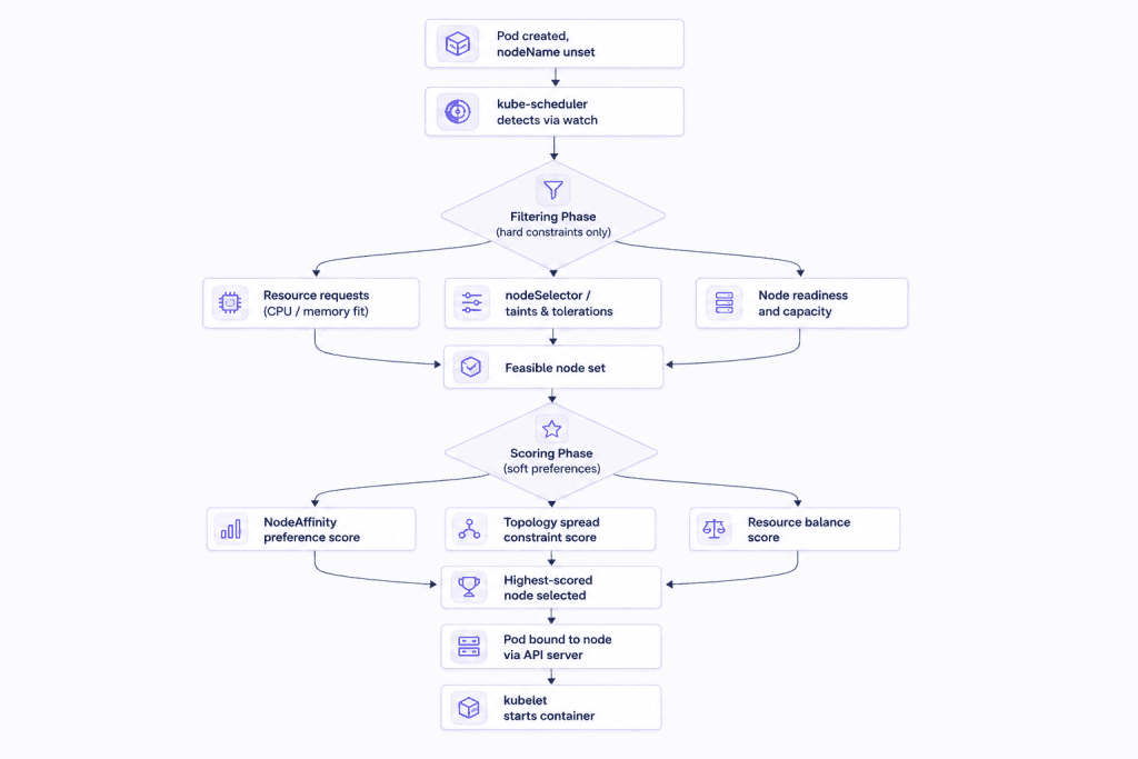
The scheduler sees nodes in exactly one cluster, and the Kubernetes scheduling framework provides no mechanism for cross-cluster pod placement. If you want a workload that runs pods in both us-west-2 on AWS and us-east1 on GCP, you need a control plane above the cluster level, a federation layer or an external orchestration system, to make that placement decision and replicate the workload into each cluster.
Multi-Cloud Networking: Why Kubernetes Clusters Don’t Talk by Default
Kubernetes clusters on different clouds can’t communicate natively because they share no network fabric, and pod CIDRs commonly overlap. Both AWS EKS and GCP GKE typically use ranges within the 10.0.0.0/8 private address space. The three main solutions (VPN mesh, Istio multi-cluster with east-west gateway, and CNI-level routing) each add their own failure domains and operational overhead.
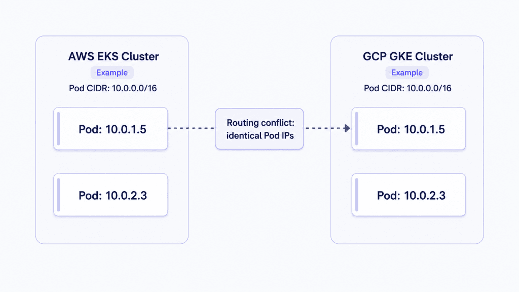
Spin up an EKS cluster and a GKE cluster without coordinating IP addressing and you’ll likely hit a CIDR overlap problem. Both platforms commonly use ranges within the 10.0.0.0/8 private address space for pods, so two pods on different clusters can end up with identical or overlapping IP addresses. 10.0.1.45 could exist in AWS and GCP simultaneously, making direct pod-to-pod routing across those networks impossible without re-addressing one of them or adding an overlay that translates addresses. Once you decide cross-cluster networking is necessary, you have three real options.
WireGuard or Tailscale VPN mesh establishes an encrypted tunnel between the clusters’ node networks. Pod traffic destined for the other cluster routes through the tunnel. Setup is relatively simple, you don’t need to change either cluster’s CNI plugin, and it works with any managed K8s offering. The trade-off is latency: every east-west packet crosses the tunnel, and for chatty microservices that talk across clusters frequently, the added round-trip adds up. You’re also managing key rotation and tunnel health as new failure domains.
Istio multi-cluster with east-west gateway is the service mesh approach. You configure a trust domain federation between two clusters (each cluster’s Istio control plane issues mTLS certificates from a shared root CA) and deploy an east-west gateway in each cluster that handles cross-cluster service traffic. The benefit is encrypted service-to-service communication with full mTLS, plus Istio’s traffic management features (retries, circuit breaking) working across the cluster boundary. The cost is significant: you need consistent Istio versions across both clusters, a working PKI for cross-cluster certificate issuance, and someone who actually knows Istio’s multi-cluster configuration model. That last requirement is rarer than you’d think.
Some CNI plugins provide cross-cluster routing at the network layer, with lower overhead than a service mesh. The problem is consistency: you need the same CNI running on every cluster, which is easy to ensure if you control the infrastructure and nearly impossible to enforce when you’re using managed K8s offerings that come with their own default CNI. EKS ships with the VPC CNI. GKE ships with its own implementation. Getting those to talk at the CNI level requires infrastructure you don’t control.
Every cross-cluster networking solution adds its own failure domain, its own configuration surface, and its own debugging burden. A VPN tunnel goes down at 3 a.m. and you spend forty minutes figuring out whether the problem is in the tunnel, the routing table, or the application. That’s the tax of DIY multi-cloud K8s, and it’s real and ongoing.
Service Discovery and Health Checks at Kubernetes Cluster Boundaries
CoreDNS resolves service names only within its own cluster. The .svc.cluster.local domain is scoped to one cluster’s service registry, meaning cross-cluster service discovery requires an external DNS federation layer or a service mesh that proxies remote endpoints locally. Health probes (liveness, readiness, startup) operate per-pod and per-cluster, with no native mechanism for coordinating health state or rerouting traffic across clusters when a remote location degrades.
CoreDNS handles service discovery inside a Kubernetes cluster. When a pod queries payment-service.billing.svc.cluster.local, CoreDNS resolves it to the ClusterIP of the payment-service Service in the billing namespace. The .svc.cluster.local domain is scoped to the cluster, baked into CoreDNS’s configuration, resolving names only from that cluster’s service registry.
A pod on your AWS cluster can’t resolve a service running on your GCP cluster via CoreDNS. Cross-cluster service discovery requires either an external DNS system that federates both clusters’ service registries, or a service mesh that abstracts the service endpoint so the application sees a local address that proxies to the remote cluster. Without one of those layers, you’re writing service endpoints as hard-coded DNS names pointing to LoadBalancer IPs, which is fine until one of them changes.
Health probe mechanics compound this problem at cluster boundaries. The three probe types in Kubernetes work at the pod level:
- Liveness probes determine whether the container is alive. A failed liveness probe triggers a container restart. The kubelet manages this and doesn’t involve the API server unless you’re watching pod events.
- Readiness probes determine whether the pod should receive traffic. A failed readiness probe removes the pod from the Service’s EndpointSlice. Traffic stops flowing to it, but the container keeps running.
- Startup probes gate liveness and readiness checks until the initial startup sequence completes. They exist to handle slow-starting applications. If you’ve deployed a JVM service and watched it restart-loop because the liveness probe fired before the JVM finished warming up, this is the fix. Set
failureThreshold: 30with aperiodSeconds: 10startup probe and your liveness check has 5 minutes before it starts running.
That JVM example is worth dwelling on. A liveness probe with initialDelaySeconds: 10 on a service that takes 45 seconds to become healthy will trigger restarts before the application finishes warming up. The kubelet handles those restarts according to the container’s restart policy; the scheduler is not making a new placement decision unless the Pod itself needs to be scheduled again. From the outside, this can look like a degraded rollout rather than a placement problem. The restart loop can run for minutes before anyone notices, because the deployment’s READY count stays above zero while at least one pod cycles through startup phases. This is why startup probes are the safer mechanism for slow-starting applications.
The cross-cluster health coordination problem is distinct. Health checks run per-pod, per-cluster. If a cluster on GCP degrades (all pods failing readiness probes, traffic being dropped), nothing in the AWS cluster’s control plane knows about it. There’s no notification, no automatic DNS failover, no traffic rerouting. The Kubernetes control plane stops at the cluster boundary. Coordinating health state across clusters and routing traffic accordingly requires a system that sits above both clusters with a global view.
What a Managed Multi-Cloud Orchestration Layer Actually Provides
A multi-cloud orchestration layer above raw Kubernetes handles cross-cluster workload placement, provides a unified service discovery namespace, and monitors health globally to route traffic away from degraded locations automatically, without requiring Istio multi-cluster, VPN tunnels, or DNS federation to be configured manually.
The previous four sections add up to a specific set of capability boundaries: the scheduler doesn’t cross cluster boundaries, cross-cluster networking requires an overlay that you manage, CoreDNS doesn’t federate, and health failover above the cluster level doesn’t exist in raw K8s. Those are features of scope, not defects. K8s was designed to solve single-cluster orchestration, and it solves that well.
Control Plane is a cloud virtualization platform that wraps AWS, GCP, Azure, and private infrastructure under a single API. That makes it categorically different from a K8s management layer like Rancher, which stops at the cluster boundary.
The core abstraction is the Global Virtual Cloud (GVC). A GVC is a named set of cloud locations where a workload runs simultaneously. Creating one looks like this:
cpln gvc create --name prod-gvc --location aws-us-west-2 --location gcp-us-east1
Every workload deployed into prod-gvc runs in both aws-us-west-2 and gcp-us-east1 simultaneously. The platform handles the replication. The GVC also generates a single TLS endpoint with latency-based geo-routing: requests from the US West Coast resolve to the AWS replica; requests from the US East Coast resolve to the GCP replica. No CoreDNS federation to configure, no external DNS operator to deploy, no Istio multi-cluster to wire up.
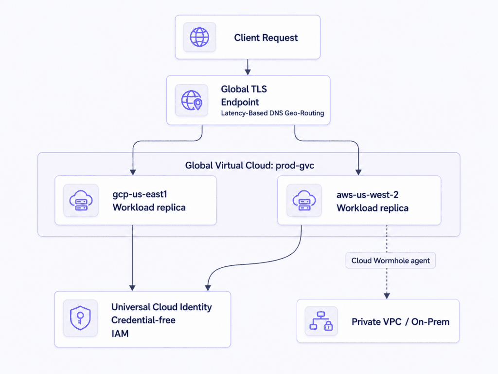
Each boundary from the previous sections maps to a named primitive:
- Cross-cloud networking: the platform fabric handles pod-to-pod communication across clouds, with no CIDR overlap to manage because you’re working above raw pod networks.
- Cross-cluster service discovery: workloads within the same GVC can reach each other via internal endpoints such as
http://hello-world.quickstart-gvc.cpln.local:8080, with no DNS federation required. Internal traffic is encrypted with mTLS. - Cross-cluster health failover: the GVC routing layer provides DNS geo-routing across configured locations and can prioritize or filter locations using settings such as
routingTierandlatencyToleranceMs. For workload-level failover, pair this routing model with application-level health and observability. - Identity: Universal Cloud Identity provides credential-free cross-cloud IAM. Your workload gets an identity that can assume AWS IAM roles, GCP service accounts, or Azure managed identities without embedding static credentials in a pod spec or Secret.
- Private network access: Cloud Wormhole agents provide outbound TCP connectivity from workloads into private VPCs or on-premises networks, without inbound firewall rules or a full VPN tunnel.
For burst scaling scenarios, the GVC spec supports KEDA (the Kubernetes Event-Driven Autoscaler) directly. If you’re scaling on queue depth, HTTP request rate, or any KEDA-supported scaler, that configuration travels with the workload spec across all GVC locations.
For teams with existing EKS, GKE, or on-premises clusters, BYOK (Bring Your Own Kubernetes) lets you attach any cluster as a named location in a GVC. You connect existing clusters to the GVC fabric and let the orchestration layer handle the cross-cluster concerns, with no workload migration required.
If you’re already managing infrastructure as code via Terraform or Pulumi, GVC and workload manifests can be expressed as resources in either. The same cpln apply GitOps model also works if you prefer YAML-driven workflows.
Deploy a Multi-Cloud Kubernetes Workload in Under 10 Minutes
Standing up a geo-redundant workload across AWS and GCP with Control Plane takes four steps: install the CLI, authenticate, create a GVC spanning two cloud locations, and deploy a container. The platform handles cross-cloud replication, TLS endpoint generation, and latency-based routing automatically, no Istio, no VPN, no DNS federation required.
These commands assume you have Node.js 18+ installed; if you’re on macOS or Linux with Homebrew, swap the install command.
Step 1: Install the CLI
# npm
npm install -g @controlplane/cli
Or for Homebrew:
brew tap controlplane-com/cpln && brew install cpln
Step 2: Authenticate and set your org
cpln login
cpln profile update default --org YOUR_ORG
Step 3: Create the GVC spanning two clouds
cpln gvc create --name quickstart-gvc --location aws-us-west-2 --location gcp-us-east1
cpln profile update default --gvc quickstart-gvc
Step 4: Create a workload
cpln workload create --name hello-world \
  --image gcr.io/knative-samples/helloworld-go \
  --port 8080 \
  --public
Verify the deployment:
cpln workload get hello-world
cpln workload open hello-world
Within a couple of minutes, the workload is running simultaneously in aws-us-west-2 and gcp-us-east1. The platform assigns a single TLS-secured global endpoint. Requests route to the closest healthy location by latency, and if one location degrades, traffic automatically shifts to the other with no DNS TTL games or manual intervention.
You defined one workload in one GVC and got geo-redundant, geo-routed, automatically failing-over infrastructure, with no Istio multi-cluster configuration, no CIDR range management, no cross-cluster VPN, and no CoreDNS federation.
Deploy a workload across AWS and GCP in under 10 minutes, start free on Control Plane
Kubernetes Multi-Cloud Orchestration FAQ
Kubernetes multi-cloud orchestration is the practice of running and managing containerized workloads across two or more cloud providers (such as AWS, GCP, and Azure) using a coordination layer that sits above individual clusters. Raw Kubernetes handles single-cluster lifecycle management. A multi-cloud orchestration platform adds cross-cluster scheduling, unified service discovery, and global health-based traffic routing.
Kubernetes was designed for single-cluster lifecycle management. Its control plane (the API server, scheduler, and controller manager) has no awareness of other clusters. CoreDNS resolves only .svc.cluster.local names within its own cluster, and the scheduler sees only nodes registered to its own API server. Cross-cluster communication requires an overlay network, a service mesh, or an orchestration layer added on top.
When two clusters use overlapping pod CIDRs (common when both use ranges within the 10.0.0.0/8 private address space), two pods on different clusters can have identical IP addresses simultaneously. Direct pod-to-pod routing between those clusters becomes impossible without re-addressing one cluster’s network or adding an address-translation overlay. This is the first concrete problem teams hit when connecting EKS and GKE clusters.
A startup probe delays liveness and readiness checks until a container completes its initial startup sequence. Use one for any application with a slow initialization phase: JVM services, services that pre-warm large caches, or anything that takes more than 10-15 seconds to become healthy. Without a startup probe, a liveness check fires before the application is ready and triggers a restart loop that can run for minutes before anyone notices.
The scheduler runs in two phases. Filtering eliminates any node that can’t satisfy the pod’s hard constraints: CPU and memory requests, nodeSelector labels, and taint tolerations. Scoring then ranks the remaining feasible nodes using soft preferences like node affinity rules and topology spread constraints. The node with the highest aggregate score is selected and the pod is bound to it via the API server.
A Global Virtual Cloud is a named set of cloud locations where a workload runs simultaneously. On Control Plane, creating a GVC and deploying a workload into it automatically replicates that workload across every location in the GVC, for example, aws-us-west-2 and gcp-us-east1 at the same time. The platform also generates a single TLS endpoint with latency-based geo-routing, so clients are automatically directed to the nearest healthy replica.
BYOK lets you attach an existing Kubernetes cluster (EKS, GKE, AKS, or on-premises) as a named location in a cloud virtualization platform’s control plane. You connect your existing clusters to the orchestration fabric rather than migrating workloads to new infrastructure. The platform then handles cross-cluster concerns like service discovery, identity, and health-based traffic routing across all attached clusters.
Platforms like Control Plane implement a Universal Cloud Identity model, where each workload is assigned a managed identity that can assume native IAM roles on each cloud (AWS IAM roles, GCP service accounts, or Azure managed identities) without storing static credentials in pod specs or Kubernetes Secrets. The platform handles credential issuance and rotation, eliminating a common source of cross-cloud security incidents.
The actual engineering challenge, the one that sends teams down 2 a.m. rabbit holes, is making Kubernetes work coherently across cloud boundaries. The scheduler doesn’t see other clusters. CoreDNS doesn’t resolve cross-cluster service names. Health failover above the pod level doesn’t exist in raw K8s. Every solution you bolt onto vanilla K8s to solve these deltas adds its own failure domain and operational surface.
Understanding those deltas precisely lets you design infrastructure that handles them by architecture rather than incident response. Whether you solve them with a service mesh, a VPN overlay, or a managed orchestration layer is a decision worth making deliberately, and ideally before something breaks.